Inline Duct Fan Placement: Inlet, Outlet and Straight Runs
Plan fan direction, unobstructed inlet and outlet conditions, service access and straight duct from the model instructions.
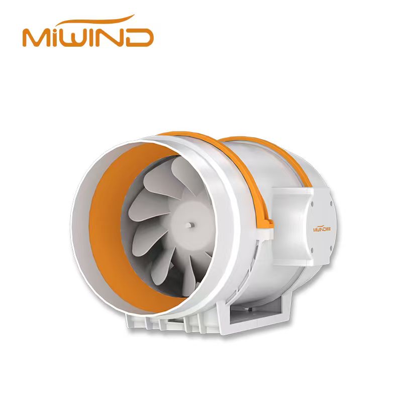
Place an inline duct fan where its inlet and outlet can receive unobstructed airflow and where the unit can be serviced. Avoid placing tight elbows, abrupt transitions, or restrictive fittings immediately beside the fan unless the model instructions allow that layout.
This guide is for OEM buyers, HVAC and MEP engineers, distributor technical sales teams, installers, and project owners planning fan location before purchase. MIWIND can review inline duct fan products, technical resources, fresh-air system planning, and project placement details submitted through Contact Us.
Use this guide as an early placement checklist before selecting a fan or preparing an installation plan. Final mounting angle, support method, clearance, wiring, service access, and straight-duct requirements should be confirmed with current MIWIND product documents, project drawings, and the qualified installation team.
Inline Duct Fan Placement Starts With Direction and Access
The first placement questions are simple:
- Where is the inlet side?
- Where is the outlet side?
- Which way must the airflow move?
- Can the fan be supported safely?
- Can the fan be inspected, cleaned, serviced, or replaced later?
- Is there enough space to connect duct, wiring, accessories, and supports?
These questions sound basic, but they prevent many weak installation decisions. A fan hidden above a ceiling, buried behind equipment, or placed where a filter cannot be serviced can create long-term airflow and maintenance problems.
Inlet Side, Outlet Side, and Service Clearance
The inlet side should receive air as smoothly as the layout allows. The outlet side should discharge into a duct path that does not immediately block or disturb the fan. Service access matters because filters, duct joints, fasteners, wiring, and the fan itself may need future inspection.
For MIWIND projects, the buyer should send the actual installation position and access constraints before asking for a final model recommendation. Orientation, brackets, supports, and wiring access are product-specific details that belong in the current manual or submittal package.
Plan Straight Duct Without Guessing Fixed Distances
Straight duct helps because smoother inlet and outlet conditions are easier to predict than disturbed airflow. Exact straight-run needs depend on the fan, duct size, fittings, accessories, flow condition, and product documentation.
A practical early-layout rule is:
Leave practical straight duct where possible, avoid abrupt disturbances close to the fan, and submit the layout when placement is constrained.
Greenheck's system effects article explains why real installations can differ from ideal fan test conditions. That is the main engineering reason placement belongs in the selection discussion, not only in the installer checklist.
Why Smoother Airflow Helps Selection Discussions
Smoother airflow can help the selected fan operate closer to the expected duty point. Poor inlet or outlet conditions can increase resistance, create turbulence, raise sound concerns, or reduce installed airflow. That is why placement connects to static pressure selection basics, even though this article is not repeating the static pressure lesson.
If the project has no room for straight duct, the buyer should say so early. A supplier cannot review the real installation if the constraint is hidden until after purchase.
Avoid Inlet Turbulence and Outlet Restriction
The inlet should not be treated as empty space. Tight elbows, abrupt reducers, dampers, filters, wall openings, or grilles immediately before the fan can disturb airflow. In some projects the fan still has to fit there, but the condition should be visible to the engineer or supplier.
The outlet also matters. A discharge path that immediately hits a wall, tight bend, closed damper, restrictive grille, or poorly sized duct can reduce performance and raise noise. The fan pushes air into the outlet system, so outlet resistance belongs in the project review.
For MIWIND inquiries, describe:
- Distance from nearby elbows, walls, filters, dampers, grilles, and transitions.
- Direction of airflow and whether the fan is supply, exhaust, transfer, or cabinet ventilation.
- Any ceiling, wall, equipment, or access limitation.
- Whether the installation is new construction, retrofit, OEM equipment, or replacement.
Match Placement to the Application
Placement is not the same for every use case. Fresh-air intake, exhaust, transfer air, cabinet ventilation, ceiling voids, and equipment-room airflow all create different priorities.
Fresh-Air Intake, Exhaust, Transfer, Ceiling, and Cabinet Spaces
Fresh-air applications may need filter access, intake protection, balanced ventilation thinking, and separation from exhaust discharge. Exhaust applications may need make-up air review and odor or heat-source context. Cabinet ventilation needs heat-source location, access, and service constraints. Ceiling voids need support, noise, and maintenance planning.
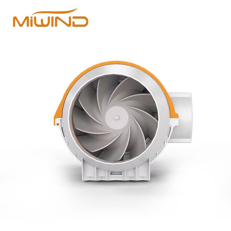
The MIWIND Duct Fan Series covers inline fans, silent ventilation models, heat-recovery products, compact duct runs, cabinet ventilation, and larger fresh-air exchange systems. Use that product path after the placement constraints are visible.
Confirm Site Context Before Comparing Fan Types
Placement can affect whether the project should compare an inline duct fan, a mixed-flow fan, a silent ventilation model, or a broader fresh-air system path. For example, a space-limited duct route may make compact inline products attractive, while a higher-resistance exhaust path may require more careful pressure review.
If the fan type is still unclear, review the mixed-flow vs centrifugal inline fan comparison. If the system is part of outdoor-air planning, review fresh-air system planning. If final support documents are needed, use MIWIND technical resources.
For placement review, send:
- Installation photo, drawing, or sketch.
- Airflow direction.
- Target airflow and estimated duct resistance if known.
- Duct length, bends, filters, grilles, dampers, and outlet location.
- Installation space, service access, nearby obstructions, and noise-sensitive areas.
- Application type, project country or region, expected quantity, and required documents.
FAQ
Can one universal straight-duct rule solve every placement problem?
No. Straight duct is useful, but exact rules depend on the fan, duct layout, fittings, accessories, and product documentation. Use the current manual or engineering review for fixed distance requirements.
Can I use another brand's mounting instruction for MIWIND products?
No. Mounting permission is product-specific. Confirm MIWIND installation requirements with current product documents.
Does placement affect fan selection?
Yes. Placement can change inlet and outlet conditions, resistance, sound, maintenance access, and installed airflow. That is why placement should be discussed before final fan comparison.
Next Step
To confirm fan placement with MIWIND, send the installation sketch or photos, airflow direction, duct path, filters, grilles, nearby obstructions, service access, target airflow, noise requirement, application type, project market, and expected quantity. MIWIND can then compare duct fan, mixed-flow, silent ventilation, and fresh-air options with the site constraints visible.