Local Exhaust Ventilation Design: Hood, Duct and Airflow Basics
Prepare source, hood, operator, cross-draft, duct and discharge details for a qualified local exhaust ventilation review.
Local exhaust ventilation design begins with the source and the airflow path, not with a fan size. A useful buyer request describes the process, hood or inlet position, operator location, cross drafts, duct route, discharge path, make-up air, and target values provided by the engineer or industrial hygiene team.
This awareness-stage checklist is for OEM buyers, distributors, MEP engineers, HVAC contractors, workshop supervisors, facility managers, and kitchen teams preparing local exhaust inputs before selecting a fan. MIWIND can route local exhaust design inputs, discuss exhaust fan products for kitchens and workshops, provide ventilation technical resources, and receive project details through Contact Us.
Use this checklist at the buyer-input stage to organize the information needed for professional design review: source location, hood or inlet position, duct route, airflow path, make-up air, and the engineering values that belong in the project brief. Capture velocity, pressure, compliance, and model-level performance still need project-specific documentation.
What Local Exhaust Design Must Define First
Start with the source. What is being generated, where is it generated, and where does it travel before capture? A bench process, cooking line, cabinet, welding station, packing area, woodworking station, or chemical process may require different review.
CCOHS ventilation introduction and OSHA's industrial ventilation chapter are useful because they frame local exhaust as a system around the source, hood, duct, fan, and discharge. Buyers can use them to structure the design brief before asking for MIWIND product guidance.
If you are new to local exhaust, start with the source-capture ventilation guide. This article focuses on the additional inputs that shape hood placement and the airflow path.
Hood Type and Placement Near the Source
The hood or inlet is where the system tries to collect unwanted air. CCOHS describes hood concepts such as enclosing, receiving, and capturing hoods. The practical buyer question is: how close can the inlet be to the source without blocking the process, the operator, cleaning, or maintenance?
Capture velocity as a design concept
Capture velocity is a design concept, not a universal number to copy into every project. It depends on the contaminant, process, distance, cross drafts, hood type, and professional design method. Buyers may have engineer-provided target values, but this article does not publish a MIWIND-specific capture velocity table.
Hood distance and open-face losses
Distance matters. A hood that is too far from the source may need much more airflow or may fail to capture the unwanted air path. Open hoods are often more sensitive to drafts and operator movement than enclosed or partially enclosed approaches.
CCOHS hood guidance is a strong source for the buyer checklist because it explains how hood type, location, airflow, and cross drafts affect collection. Use it to ask better questions, not to approve a design.
Keep the Airflow Path Away From the Operator Breathing Zone
The airflow path should not pull contaminants across the operator's breathing zone before reaching the hood. Ask for a sketch showing the source, operator position, hood or inlet, supply diffuser, doors, windows, fans, and normal work motion.
This is especially important in workshops and factory retrofits where a fan may be added after the process already exists. If the fan pulls air across the worker, customer, cookline, or adjacent workstation, the airflow path needs professional review.
Cross Drafts, Doors, Supply Diffusers, and Process Airflow
Cross drafts can disturb capture. Doors, windows, supply diffusers, cooling fans, process fans, compressed air, moving carts, open service windows, and make-up air discharge can all change where fumes, heat, smoke, dust, or odor travels.
For kitchen-adjacent projects, make-up air should be discussed carefully but not turned into a separate article here. Review make-up air and exhaust balance when pressure and replacement air are the main issue.
Duct Route, Elbows, Branches, and Discharge Path
After the source and hood path are defined, the duct route decides what resistance the fan sees. Collect:
- Duct length, diameter or section size, and material.
- Elbows, branches, reducers, transitions, dampers, filters, and access points.
- Whether the route is direct, concealed, vertical, horizontal, or shared.
- Discharge location and possible re-entry or neighbor concerns.
- Maintenance access and cleaning requirements.
CCOHS duct guidance supports this routing mindset. For MIWIND, this is where exhaust fan products for kitchens and workshops can enter the conversation after the duty conditions are described.
Fan Selection Inputs: Airflow Target, Pressure, and Duty Point
Fan selection should follow project inputs. The buyer should send airflow targets, static pressure estimates, and duty-point requirements only when a qualified project source has provided them. If those values are missing, send drawings, photos, duct details, and source notes so the support conversation can identify what is still unknown.
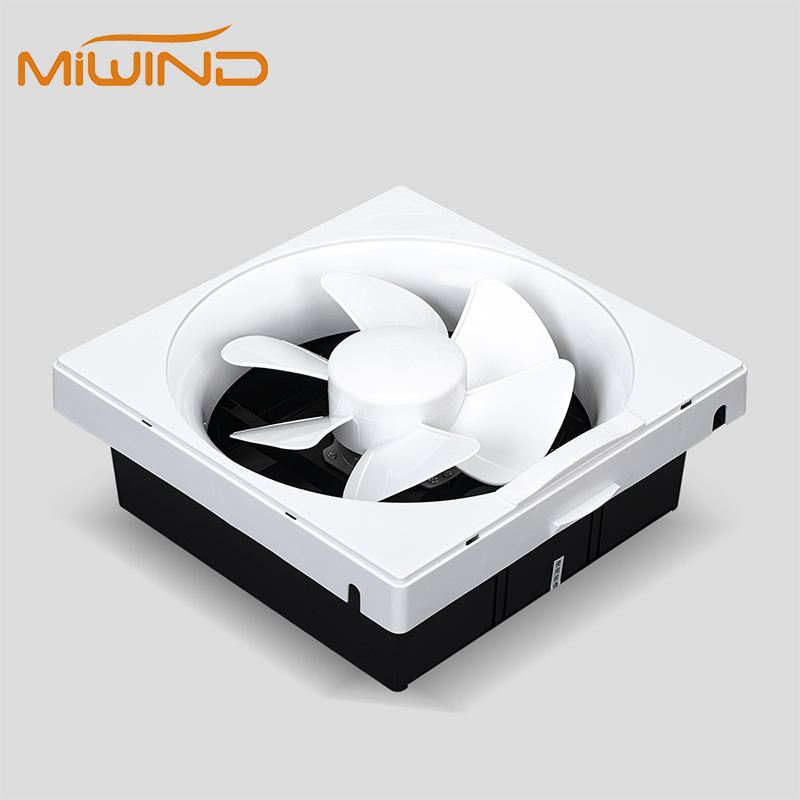
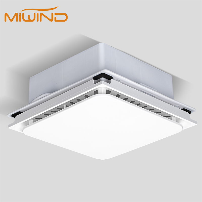
MIWIND's exhaust fan series can support discussions around wall, roof, and ducted exhaust fan products for commercial and industrial ventilation. It should not be presented as a substitute for professional LEV calculations or commissioned verification.
Testing, Commissioning, and Troubleshooting Signals
LEV systems may need measurement, commissioning, and maintenance after installation. CCOHS troubleshooting guidance and the HSE HSG258 page are useful because they reinforce the idea that local exhaust performance is verified and maintained, not assumed.
In a retrofit, ask for signs such as:
- Hood too far from the source.
- Operator between source and hood.
- Cross draft blowing across the process.
- Duct damage, blockage, leakage, or dirty filters.
- Low airflow after installation.
- Fan noise, vibration, or poor discharge location.
- Missing make-up air path.
For an installed inline fan with low airflow, see the inline fan troubleshooting guide.
FAQ
Is local exhaust design the same as fan sizing?
No. Fan sizing is one part of the system. The source, hood type, hood placement, operator position, cross drafts, duct route, discharge, make-up air, and commissioning all matter.
Can MIWIND provide exact capture velocity or hood distance here?
Not from this article alone. Use engineer-provided target values and project-specific review for any final airflow or hood-distance decision.
When should a professional engineer or industrial hygiene reviewer be involved?
Use qualified review when exposure, hazardous material, grease, fire, life safety, regulatory compliance, or worker safety is part of the project requirement.
Next Step: Send Exhaust Design Inputs
Use send exhaust design inputs after collecting the source or process type, contaminant form, hood or inlet sketch, hood distance, operator position, cross drafts, duct length, duct diameter, elbows, discharge route, existing fan details, make-up air path, and any engineer-provided target values.